Bond preparation
Can Laser Cleaning Improve Adhesive Bonding? A Test Plan for Metal and Composite Parts
Use a coupon-to-production test plan to evaluate laser cleaning before adhesive bonding on metal or composite parts without relying on appearance alone.
14 min readBy LaserLuma technical team
Published
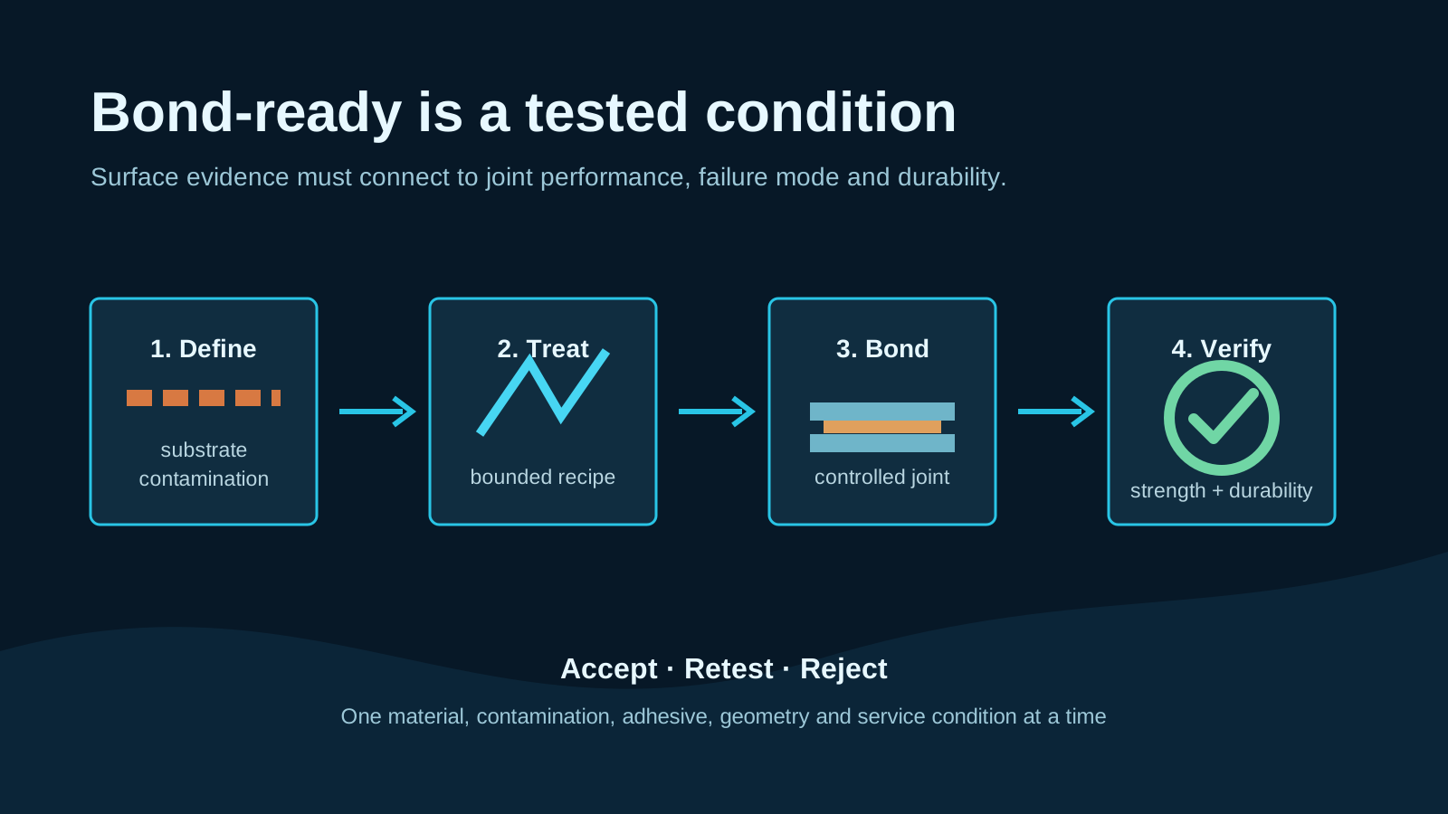
Laser cleaning can improve adhesive bonding when it removes the relevant contamination and creates a surface that the selected adhesive can wet without unacceptable substrate damage. It can also produce a weak or unreliable joint when the treatment is too mild, too aggressive or transferred to a different material, contamination or adhesive without validation. The useful decision is therefore not whether a laser can make the surface look clean. It is whether a documented laser process can repeatedly produce an accepted bonded joint after the required environmental exposure.
Laser cleaning can improve bonding—but only inside a verified process window
Adhesive bonding depends on the complete interface: substrate, contamination, surface chemistry and topography, adhesive rheology, application time, cure, joint design and service environment. Laser treatment changes only part of that system. A useful trial must show that the treatment removes the weak boundary layer, leaves an adhesive-compatible surface and does not create heat damage, loose residue or a surface that changes before bonding.
A 2015 study of laser- and plasma-treated metallic adherends found that increased roughness helped the bonded joint only when the adhesive could wet the treated surface sufficiently to use that topography for mechanical interlocking. That is an important boundary for equipment buyers: rougher is not automatically better, and a low contact angle is not a substitute for testing the actual joint.
The accepted result must be written for one defined bond system. A parameter set demonstrated on one aluminium alloy and epoxy cannot be assumed for stainless steel, coated metal, thermoplastic composite or carbon-fibre epoxy. Treat published results as evidence that a test pathway can work—not as a transferable machine recipe.
| Observation | Useful for | Does not prove |
|---|---|---|
| Clean appearance | Locating obvious residue, missed areas or discoloration. | Chemical cleanliness, adhesive compatibility or durable bond strength. |
| Contact angle or test liquid | Comparing wetting behavior under a controlled method and timing. | Strength, failure mode or long-term durability of the real joint. |
| Roughness or microscopy | Recording texture, local damage, resin removal and repeatability. | That the selected adhesive fills the texture or creates an accepted interface. |
| Lap-shear or another joint test | Comparing mechanical response for a defined specimen, adhesive and test condition. | Every production geometry, load case or service environment. |
| Aged joint and failure record | Testing whether the prepared interface remains acceptable after a relevant exposure. | Conditions outside the chosen exposure, material and process window. |
Evidence: Mandolfino et al.: laser and plasma cleaning of adhesive joints
Review laser cleaning for automotive partsFreeze the bond system before testing the laser
Begin with the bonded assembly, not the laser source. Name the substrate grade and condition, adhesive or sealant, primer and cure route, joint geometry, bond-line control, expected loads, service environment and the organization responsible for acceptance. If any of those inputs are still open, the laser trial is exploratory rather than a qualification test.
Use representative contamination. A machined aluminium housing carrying cooling lubricant is a different cleaning problem from a steel bracket with storage oil, a composite panel with release-agent residue or a repaired surface with sanding dust. Include the realistic contamination amount and aging condition where possible, plus an untreated reference and the current approved preparation method.
Control the time between treatment and bonding. Surface energy and contamination can change through handling, airborne deposition, humidity or storage. Record gloves, fixtures, packaging, maximum open time, primer timing and any cleaning after laser treatment. A coupon that is bonded immediately in a laboratory may not represent a part that waits through a production shift.
- Substrate: exact alloy, polymer or composite system, finish, thickness and prior processing.
- Contamination: type, amount, distribution, age and the method used to create the test condition.
- Bond system: adhesive, primer, mix and application method, bond-line thickness, cure and handling window.
- Joint requirement: geometry, load case, failure-mode expectation, environment and acceptance authority.
- Controls: reference surface, replicate count, randomization, inspection method and retest rule.
Separate cleaning, activation, texturing and over-processing
A laser can remove a contaminant, modify surface chemistry, create microtexture or remove part of the substrate. Those effects can occur together, but they are not interchangeable. Define the intended treatment objective and the reject boundary before varying power, pulse energy, overlap, scan speed, wavelength, focus or number of passes.
For metal, the boundary may include unacceptable melting, re-solidified material, excessive oxidation, loose particles, distortion or a texture the adhesive does not fill. For a fibre-reinforced polymer, the boundary may include resin decomposition, exposed or damaged fibres, delamination and a heat-affected interface. The correct window is wide enough to remove the target contamination and narrow enough to protect the surface needed by the adhesive.
Research on aerospace CFRP illustrates this distinction. In a UV-laser cleaning study, a smoother condition that removed release-agent contamination without aggressively exposing fibres produced a stronger joint than the more aggressive tested condition. Other composite research has used controlled ablation and long-duration aging to evaluate a deliberately prepared surface. The studies support parameter control and joint testing; they do not establish one universal wavelength or energy density.
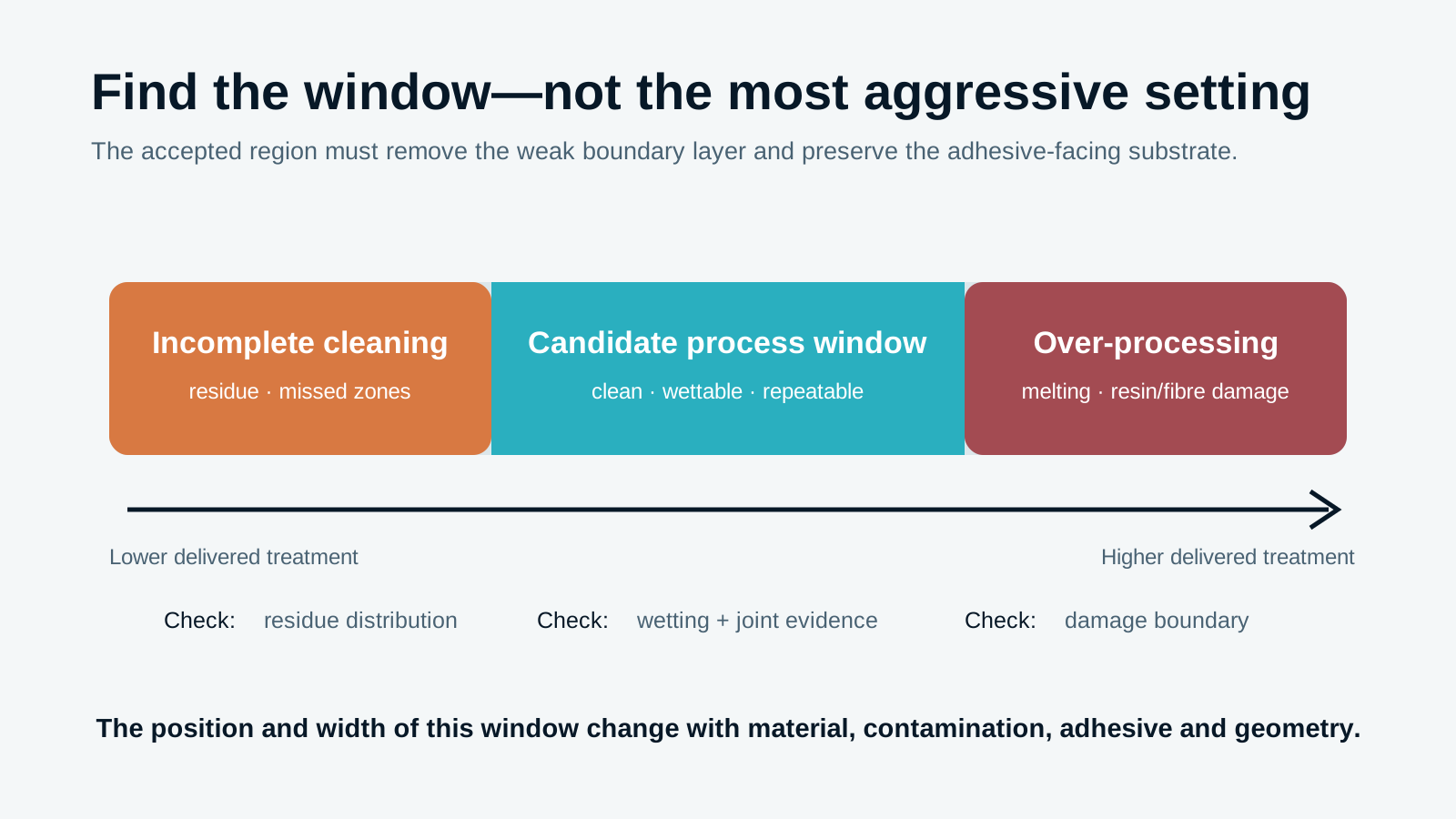
- Reject or retest when contamination remains in the intended bond area.
- Reject or retest when microscopy shows loose redeposit, cracks, melted features, resin damage or unintended fibre exposure.
- Do not optimize one proxy, such as roughness or contact angle, without checking the bonded joint.
- Record the full recipe and beam-delivery geometry so the condition can be reproduced.
Evidence: Rauh et al.: UV-laser cleaning and CFRP surface characterization · Palmieri et al.: laser preparation for adhesive bonding of CFRP
Compare laser cleaning process familiesBuild a metal coupon matrix around real contamination
A useful metal study changes one controlled group of inputs at a time. Include an as-received or deliberately contaminated reference, the current approved preparation, and multiple laser conditions that bracket incomplete cleaning and the suspected acceptable window. Keep adhesive batch, application, cure, joint dimensions and testing conditions consistent enough for comparison.
For aluminium or stainless steel, surface checks may include residue analysis appropriate to the contaminant, contact angle under a documented liquid and timing, roughness, microscopy and surface chemistry when available. These checks explain the interface but do not replace a joint test. A 2024 comparison of aluminium and stainless steel surface preparations measured wettability, roughness and lap-shear behavior and showed that results varied with both material and adhesive.
An automotive study on AA5754 deliberately contaminated with cooling lubricant connected surface-monitoring measurements, laser treatment, lap-shear testing and fracture patterns for one RTV silicone system. The transferable method is to correlate a measurable cleaning signal with the accepted joint—not to reuse the study's laser threshold on a different machine, contaminant or adhesive.
| Group | Surface condition | Checks | Decision use |
|---|---|---|---|
| A: contaminated control | Representative oil, lubricant, oxide or process residue; no cleaning. | Residue method, wetting check, joint test and failure mode. | Shows how the contamination affects this bond system. |
| B: approved reference | Current qualified mechanical, chemical or plasma preparation. | Same surface and joint evidence as the laser groups. | Provides the relevant benchmark rather than an untreated coupon alone. |
| C: lower laser boundary | Condition expected to leave some contamination or weak-boundary material. | Residue distribution, microscopy, wetting and joint response. | Locates the incomplete-cleaning boundary. |
| D: candidate window | One or more repeatable conditions expected to clean without harmful surface change. | Full surface, joint, failure-mode and relevant aging evidence. | Identifies conditions worth confirming with more replicates. |
| E: upper laser boundary | Condition expected to show excess thermal or morphological change. | Microscopy, surface chemistry where relevant and joint response. | Locates the over-processing boundary. |
Evidence: Wahl et al.: monitored laser cleaning before automotive silicone bonding · Zdravković et al.: metal surface preparation, wettability and bonded joints
Frame an automotive-parts evaluationProtect the resin–fibre system when testing composites
Composite preparation needs a material-specific boundary because the top resin, fibres, sizing and release-agent residue can respond differently to wavelength, pulse duration and fluence. Removing contamination is not the same as removing the resin-rich layer. Exposed fibres may be intentional in one qualified process and unacceptable damage in another.
Start with microscopy or another suitable surface inspection before bonding. Record whether resin remains over the fibres, whether the treatment creates pits, cracks, lifted fibres or delamination, and whether the geometry causes local overexposure. Do not infer bulk integrity from a flat coupon when the production part has corners, thickness transitions or curved features.
Use the adhesive supplier's and bonding authority's joint method, then retain fracture surfaces for classification. A higher peak load with a new failure location is not automatically an acceptable result. The failure mode, scatter and performance after relevant moisture or temperature exposure can matter more than a single unaged average.
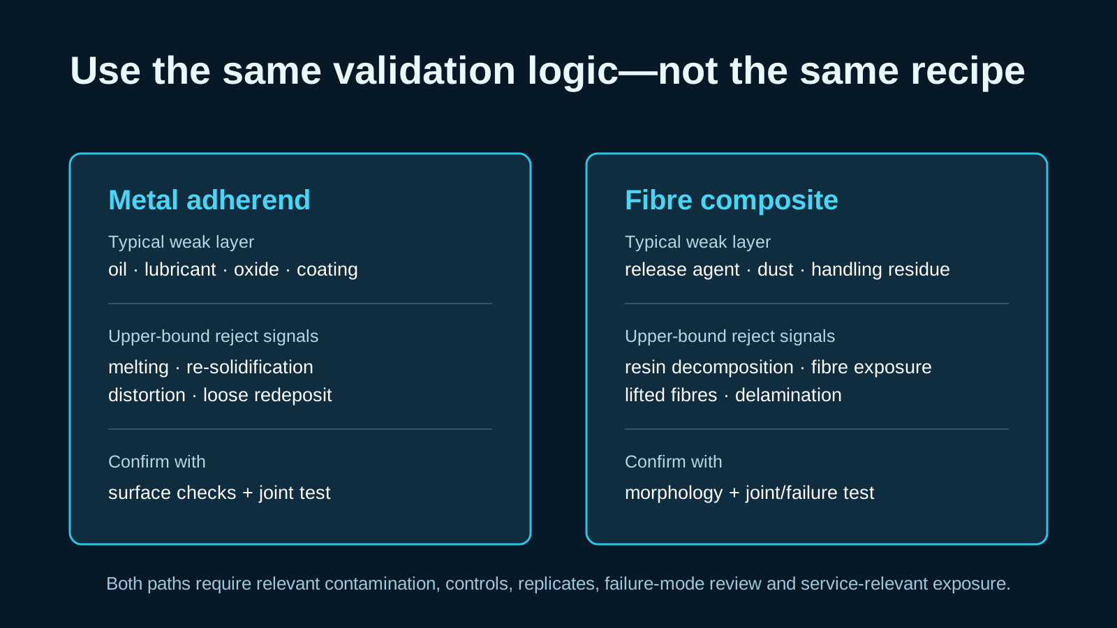
| Test concern | Metal adherend | Composite adherend |
|---|---|---|
| Weak boundary layer | Oil, lubricant, oxide, coating or handling residue. | Release agent, peel-ply transfer, machining dust or handling residue. |
| Over-processing signal | Melting, re-solidification, distortion, excessive oxide or loose redeposit. | Resin decomposition, unintended fibre exposure, lifted fibres or delamination. |
| Useful surface evidence | Residue check, wetting, roughness, microscopy and chemistry as required. | Contamination mapping, resin/fibre morphology, wetting and microscopy. |
| Joint evidence | Defined joint test, scatter, failure surface and relevant aging. | Defined joint or fracture test, failure location and relevant hygrothermal aging. |
Evidence: Rauh et al.: smooth cleaning versus fibre-exposing CFRP treatment · NASA Langley: controlled laser treatment of structural composites
Discuss a representative composite sampleUse an evidence ladder from surface checks to durable joints
Approve each level for what it can prove. Level one confirms that the treated surface is physically consistent and free from defined reject defects. Level two checks residue, wetting and other surface properties relevant to the adhesive. Level three tests the actual bonded specimen and records both performance and failure mode. Level four checks whether the joint and process remain acceptable after the service-relevant environment and production transfer.
Surface proxies are valuable for screening and control because they can be faster than destructive joint tests. Their acceptance limits should be established by correlation with the bonded-joint result. Once that relationship is demonstrated, a production process can use suitable surface monitoring with scheduled destructive confirmation instead of assuming that every clean-looking part is bond-ready.
Choose durability exposure from the real service and qualification plan. Palmieri and co-authors evaluated laser-prepared CFRP joints through a three-year accelerated hygrothermal program, illustrating why unaged strength alone may be incomplete. That does not mean every bond requires the same temperature, humidity or duration; the responsible bonding authority must define the applicable exposure.
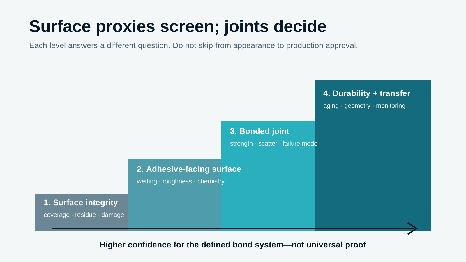
| Level | Evidence | Typical decision |
|---|---|---|
| 1. Surface integrity | Coverage, residue, microscopy, damage boundary and recipe repeatability. | Reject obvious incomplete cleaning or over-processing. |
| 2. Adhesive-facing surface | Wetting/contact angle, roughness, surface chemistry or contaminant signal as applicable. | Screen candidate conditions and explain interface changes. |
| 3. Bonded joint | Defined mechanical test, replicate scatter, fracture surface and failure mode. | Select a candidate process for confirmation. |
| 4. Durability and transfer | Relevant environmental exposure, production geometry, monitoring and change control. | Qualify, retest with limits or reject for the intended application. |
Evidence: Palmieri et al.: joint testing and hygrothermal aging after laser preparation · Wahl et al.: correlation of cleaning monitoring with adhesion behavior
Transfer the process with monitoring and change control
A coupon recipe is not yet a production process. Confirm beam incidence, focus tolerance, scan-path overlap, edge behavior, fixture shadowing, part variation, extraction direction and the time between treatment and adhesive application on the real geometry. Recheck the upper and lower process boundaries where curvature or robot motion changes energy delivery.
Freeze the variables that define the accepted state: machine and optic, wavelength and pulse regime, spot and focus method, scan speed and overlap, pass count, part orientation, contamination range, extraction arrangement, handling and maximum open time. Define which change triggers a partial confirmation and which change requires a new qualification.
Monitoring should detect the failure modes that matter. An optical or spectral signal may be useful when it has been correlated with contamination removal and the accepted joint, as shown in the automotive lubricant study. It should not become a decorative dashboard metric. Keep reference coupons, scheduled destructive tests, filter and extraction checks, recipe access control and traceable records appropriate to the risk of the bond.
- Record a recipe ID, machine/optic identity, software revision and approved parameter limits.
- Define surface-monitoring method, sampling frequency, alarm limit and response.
- Control part handling, storage, time-to-bond, adhesive batch, mix/application and cure records.
- Retain joint-test and fracture-mode evidence for periodic confirmation.
- Trigger review when the substrate, contamination, adhesive, geometry, extraction, optic or motion path changes.
Evidence: Wahl et al.: inline-capable monitoring of an automotive cleaning process · NASA Langley laser surface-treatment process research
Review automated laser cleaning pathsAsk suppliers for a documented bond-preparation trial
A useful supplier trial ends with evidence and limits, not only before-and-after photographs. Send representative adherends and contamination, identify the adhesive and existing preparation, and state who will make and test the bonded specimens. If the supplier is not responsible for adhesive qualification, record that boundary explicitly.
Request the full tested configuration, parameter window, surface observations, joint-test method, individual results or useful distribution, fracture photographs, reject conditions and any environmental exposure. Ask which parts of the process were measured and which remain assumptions. Keep the untreated and current-process controls so the result can be interpreted.
Use an accept, retest or reject decision. Accept only the defined candidate for the next validation stage. Retest when the result is promising but the process window, scatter, failure mode, durability or production geometry is unresolved. Reject when the contamination remains, the substrate exceeds its damage boundary, the joint misses its requirement or the controls cannot be implemented consistently.
- Representative substrate, surface history and contamination range.
- Adhesive, primer, joint geometry, cure and responsible bonding authority.
- Current preparation and untreated controls.
- Laser configuration, bounded recipe and surface evidence.
- Joint-test results, scatter, fracture surfaces and applicable aging.
- Production monitoring, handling window, change triggers and known limitations.
FAQs
Is laser cleaning good for adhesive bonding?
It can be a suitable surface-preparation process when it removes the relevant contamination, preserves the required substrate condition and produces an accepted joint with the selected adhesive. Suitability must be demonstrated for the material, contamination, adhesive, geometry and service environment; appearance alone is not enough.
Does a lower contact angle prove that a bonded joint will be stronger?
No. Contact angle can help compare wetting under a controlled method, but joint strength also depends on surface chemistry and topography, adhesive behavior, application, cure, geometry and environment. Correlate the surface measurement with the actual joint test and failure mode.
Can the same laser recipe be used on aluminium, steel and CFRP?
Do not assume so. Metals and composites have different contamination, absorption, thermal response and damage boundaries. Even two metals or two composite systems can require different recipes. Revalidate when the substrate, surface history, contamination or adhesive changes.
Does laser cleaning remove the need for a primer?
Not automatically. Primer use belongs to the qualified adhesive and corrosion-protection system. A laser trial should compare the complete intended bond process and follow the adhesive supplier's and bonding authority's requirements rather than silently deleting a primer step.
What should I send for a laser cleaning adhesive-bonding test?
Send representative substrate and contamination, the adhesive and primer, current preparation, joint geometry, cure, service environment, acceptance test and responsible approver. Include difficult production geometry and the expected time between cleaning and bonding.